|
Control System
|
Full Brochure (4.9MB) |
The system is designed, from the ground up, with unprecedented customization and controls that result in accuracy, stability, and usability that challenges the competition.
Our competition tries to meet the needs of everyone with one single user interface. Our approach is unique. We provide the flexibility and tools to design screens and panels that meet the needs of individual labs, and individual tests. Sliders, meters, labels, lights and buttons can be located and defined on custom panels, and a button can operate a Block Program.
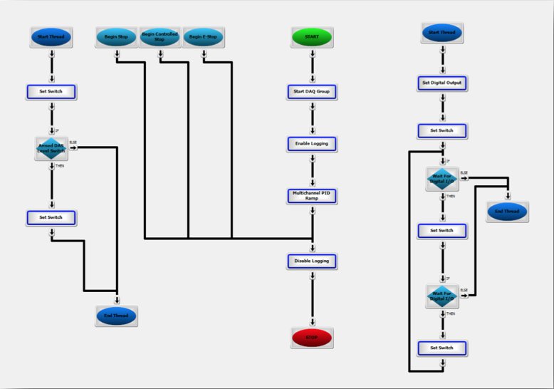
This is a program that is graphically built using a series of steps, defined in a flow-based diagram, that can perform simple or very complex multi-threaded tasks. You may define a button to turn on a hydraulic manifold, or you may define it to perform a complete test.
Once the user-interface has been built, operators simply select from a menu of pre-defined screens that conveniently provide them with all the parameters they need to run their test, without presenting them with things that they do not need. The user interface can be built by BIA West engineers, or you may choose to build them or modify them yourself.
 With the BIA West controller servo loop, there is no concern for loop-closure rates or bit resolution. These are both virtually infinite. However, because the loop is tuned and optimized digitally, the benefits of direct digital control are still there. This provides a comprehensive solution.
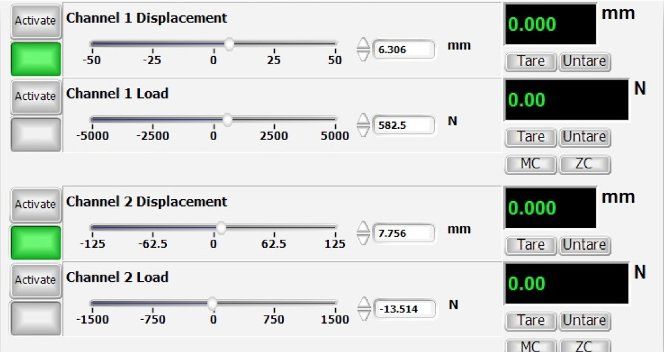
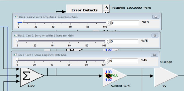
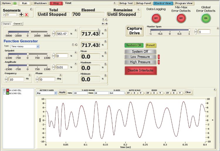
The set up and operation of the controller is performed using a PC, running Windows®. The servo loop is set up using a graphical display that provides a clear, easy to understand representation of the configuration. All the servo loop parameters can also be adjusted using the custom panels, so that one single screen can be created for tuning the loop, for example, complete with a function generator, PID controls, and scope. This keeps the operators away from any unnecessary details that can lead to dangerous mistakes.
For example, if you have developed your own hybrid simulation code, and you would like to use a dSPACE controller, it is easily interfaced to the Bia West control system using an external analog input. We provide the conditioned analog transducer outputs. You do not have to worry about digital protocols, latency, or quantization errors. The signal from your outer-loop controller will be fed directly to the actuator, and you will get the analog response back. A very significant and unique benefit.
It is called Real Time Active Control (RTAC). This is an algorithm that takes your target signal, which could be a sine wave or a realtime signal, such as an earthquake or road profile, and reproduces it, point-by-point, with high accuracy. RTAC is set up via a simple tuning screen. Once the gains are established, reproduction of the signal can be performed quickly, and with very little effort. Contrast this with competing algorithms, that use the long process of system identification and iteration to perform the same task. Typically, frequency-domain-based iterative techniques can take days to set up, and require highly experienced controls engineers. RTAC takes minutes, and can be done by anyone.
RTAC can be run in a ‘mixed mode.’ This means that you can select one transducer for the actuator closed-loop, and another for the RTAC closed-loop. For example, users would typically run the actuator in displacement control, while reproducing acceleration with RTAC.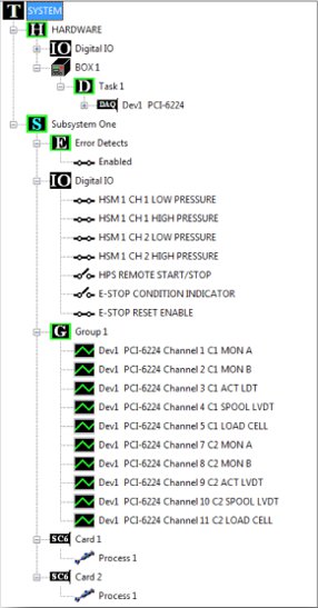
There is no need to launch a separate ‘builder’ application. All the resources that are in the system and assigned to a station can be easily viewed at any time. There is no theoretical limit to the number of stations that can be defined (whithin the capabilities of the hardware). The Hardware section contains the available items while the station configurations are displayed at a glance from expandable groups. Station resources are assigned with a simple Station Hardware Setup dialog. There is no need to shut down the software and launch another application. The software is designed to work across physical chassis boundaries too. It is possible to define stations using channels from other networked chassis. This provides for limitless ways of configuring the stations. Another unique benefit of the Bia West controller software.
The chassis is divided into two sections: one, the Servo Control section for the closed-loop controls and data acquisition; the other, called the Process Control section, for the high-current needs of solenoids. Each section has its own power supply.
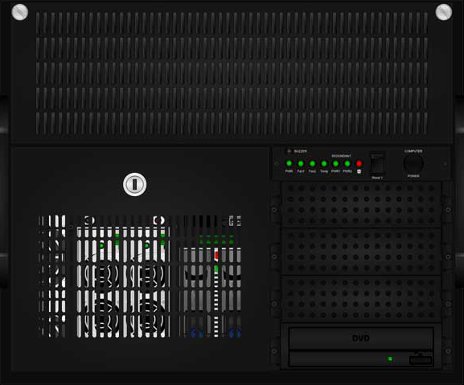
If one power supply has problems, it automatically switches to the other (and vice-versa), and issues a warning. You can continue to run your test while you replace the defective part. For easy replacement, the individual supplies can be removed from the chassis with one simple button. They are kept behind a locked panel for security. Also behind the locked panel, is a removable hard drive. This is the system disk. It can be removed and cloned, so that you have a secure backup. If the disk drive fails, you simply swap it for its clone, and you can continue testing without interruption.
The IO panel is highly configurable, and can be matched to any of your specific logic needs. The Process Control section also has an excitation module for devices that require conditioned DC power, such as LDTs. This module can provide +24VDC, ±15VDC, or +5VDC. The power supply is able to meet the high current needs of all the solenoids along with the high precision needs of external devices.