Structural Test Tables

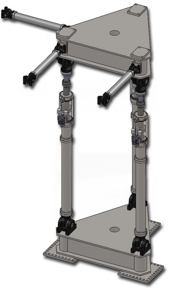
Multi degrees of freedom tables can be used to statically load structural components
 BIA West builds systems that mount to strong walls and floors, to allow civil engineers to evaluate the performance of structures under various static, or slowly varying dynamic load conditions.
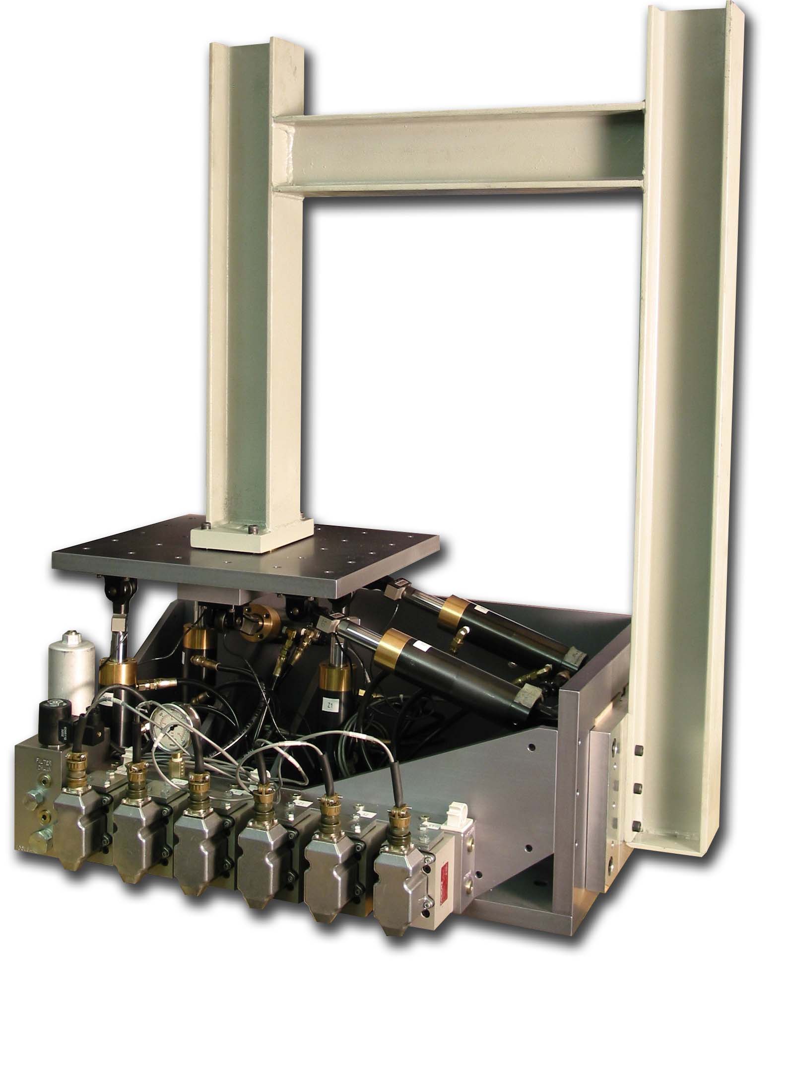
The specimen, typically a beam or column, is fixed to the table at one end, and to a strong wall or strong floor at the other. The loading tables, which are typically six degrees of freedom, are then programmed to apply forces to the specimens.
 With the open architecture of the BIA West Control System, it is straightforward to interface the system with analytic models, allowing the physical structures to be tested from within a virtual environment. BIA West was directly involved in the pioneering experiments for NEESGrid in 2002-2006. Using this network, several components can be tested together in various laboratories across the country, to simulate a large integrated structure. Two frameworks have been developed for this ‘Pseudo Dynamic’ testing: SIMCOR and OpenFresco. BIA West is able to work with both. For full Real Time Hybrid Simulation (RTHS), we interface with an xPC running Simulink.

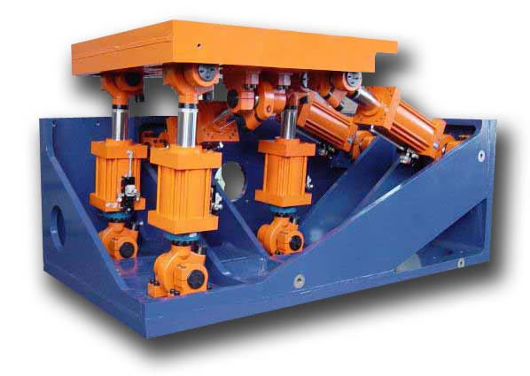
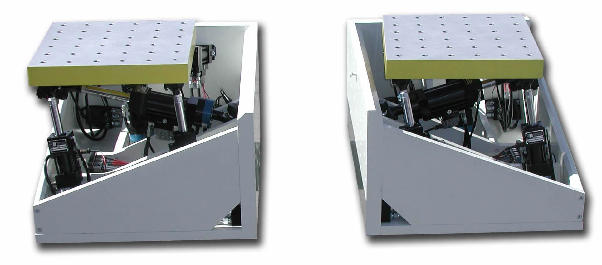
BIA West, in association with University of Illinois Urbana Champaign, has developed a family of 6 degree of freedom motion bases to simulate loading boundary conditions. Using a boxed frame, the system provides a very stiff reaction to ground, which is essential for precise measurements of component deflections.
 The boxes provide a modular solution to the need for a unitized loading platform that can be mounted to strong-walls in any orientation, from one of three sides. For example, columns can be mounted to the strong floor, with the LBCB on the top, grounded to one of the walls. Multiple units can be tied together and programmed in one unified plane using our highly configurable Multi-Degree-of-Freedom (MDoF) control algorithm.
The Load Boundary Condition Box (LBCB) ranges in size from full scale testing of large civil engineering structural elements to 1:5 scale models. The scale models are used for instructional purposes and to develop test protocols and control strategies in preparation for full scale testing. The closed loop controls, sensors and hydraulic subsystem are basically the same, the only difference is the size of the servo mechanical subsystem. User experience is identical on the scale model systems. Other form factor units are available for standalone applications.
The LBCB may operate in displacement, or mixed mode load control. With mixed mode, the control loop itself is in displacement control, but we wrap a digital load loop around it, giving the best of both worlds: tight displacement control, while commanding load.
